Get a 30-day Simcenter 3D trial
Try Simcenter 3D tools today.

Explore our downloads to learn more about Simcenter 3D and how it can help you address complex engineering challenges by enhancing simulation efficiency. As one of the most comprehensive, fully-integrated CAE solutions available, Simcenter 3D is your gateway to advanced engineering capabilities.
-3.png)

Try Simcenter 3D tools today.
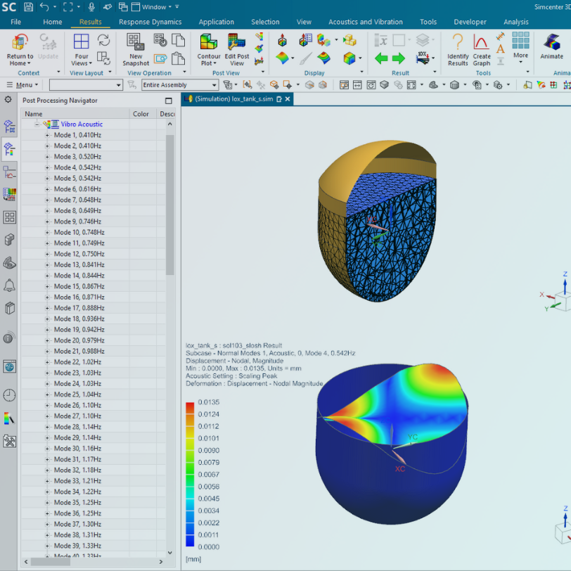
Siemens Simcenter 3D software is an advanced and powerful CAE environment. Quick and easy simulation and analysis are achievable with its extensive geometry editing capabilities, associative simulation modelling, and multi-discipline solutions.
Emixa supports you every step of the way, with decades of experience and a talented team to help transform your business.
Simcenter 3D offers efficient laminar composite modelling using zone-based and ply-based techniques. It maintains model associativity with the geometric design and collaborates seamlessly with Fibersim composites engineering software.

Try Simcenter 3D tools today.

%2015%25.png)

%2015%25-19.png)